การติดตั้งผนังวิดีโอ LCD ไม่ได้เป็นเพียงเรื่องของการแก้ไขหลายจอแสดงผลกับผนังโครงสร้างการติดตั้งจะกำหนดว่าหน้าจอสามารถจัดตำแหน่งได้อย่างถูกต้องหรือไม่ไม่ว่าสายเคเบิลจะได้รับการป้องกันหรือไม่ช่างเทคนิคสามารถเข้าถึงแผงในระหว่างการบำรุงรักษาได้หรือไม่และสามารถให้บริการผนังสำเร็จรูปได้โดยไม่รบกวนพื้นที่โดยรอบหรือไม่
ปัญหาเหล่านี้มีความสำคัญมากขึ้นเมื่อมีการติดตั้งผนังวิดีโอในผนังสื่อค้าปลีกห้องควบคุมห้องประชุมล็อบบี้ต้อนรับศูนย์นิทรรศการหรือภายในสำเร็จรูปอื่นๆที่มีการเข้าถึงด้านหลังจำกัดโครงสร้างแบบคงที่หรือด้านหลังแบบเดิมอาจต้องมีทางเดินบำรุงรักษาด้านหลังหน้าจอในผนังปิดภาคเรียนห้องแคบหรือคุณลักษณะทางสถาปัตยกรรมในตัวพื้นที่อาจไม่มีอยู่
วงเล็บการบำรุงรักษาด้านหน้าแบบไฮดรอลิกได้รับการออกแบบมาสำหรับโครงการที่บริการเข้าถึงจากด้านหน้าเป็นส่วนสำคัญของแผนการติดตั้งกลไกสามารถช่วยควบคุมการเคลื่อนไหวของส่วนการติดตั้งในขณะที่จุดปรับช่วยให้ติดตั้งจัดผนังจอแสดงผลในระหว่างการว่าจ้างอย่างไรก็ตามวงเล็บจะต้องจับคู่กับรูปแบบการแสดงผลโครงสร้างผนังโหลดรวมเส้นทางสายเคเบิลและการกวาดล้างบริการที่จำเป็น
ใครคือ qtenboard? Qtenboard เป็นโรงงานผู้ผลิตที่เชี่ยวชาญด้านโซลูชันผนังวิดีโอ LCD ครอบคลุมตั้งแต่การออกแบบการผลิตการบูรณาการระบบไปจนถึงการให้บริการสนับสนุนระยะยาวด้วยประสบการณ์กว่า20ปีในเทคโนโลยีการแสดงผลแบบมืออาชีพฐานการผลิตที่เป็นเจ้าของตัวเองขนาด330 000m ² พร้อมสายการผลิตภายในอาคารเต็มรูปแบบ (SMT, การประกอบ LCD, การสอบเทียบ, และการทดสอบอายุ) และผลิตภัณฑ์ที่ใช้งานในกว่า100ประเทศ qtenboard มอบระบบผนังวิดีโอ LCD ที่สมบูรณ์สำหรับโครงการวงเล็บไฮดรอลิกซึ่งหมายความว่าพันธมิตรที่รับผิดชอบหนึ่งรายที่มีกระบวนการผลิตเอกสารการจัดการคุณภาพ ISO9001การรับรอง ce/fcc/rohs.
คู่มือนี้เขียนขึ้นสำหรับผู้รวมผนังวิดีโอ LCD, ผู้รับเหมา AV, ผู้ติดตั้งแรงดันต่ำ, ผู้จัดจำหน่าย, ทีมทรัพย์สินเชิงพาณิชย์และผู้จัดการการจัดซื้อโครงการมันอธิบายสิ่งที่จะยืนยันก่อนการติดตั้งวิธีการเปรียบเทียบการบำรุงรักษาด้านหน้าและโครงสร้างบริการด้านหลังวิธีการติดตั้งและปรับวงเล็บไฮดรอลิ, และสิ่งที่ควรจะรวมอยู่ในรายการตรวจสอบการส่งมอบในทางปฏิบัติ
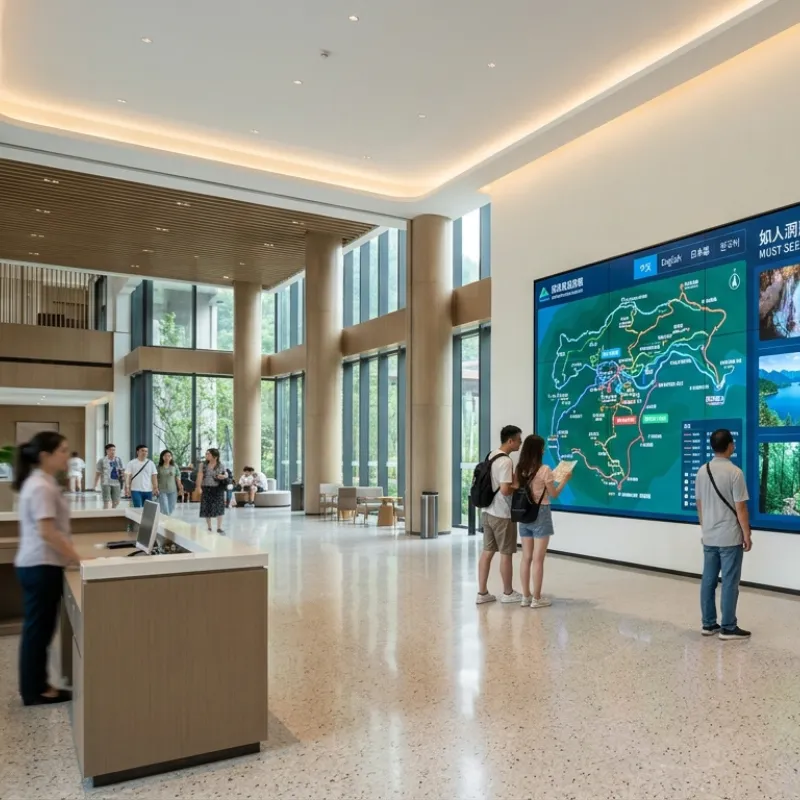
สรุปก่อน: โครงสร้างการบำรุงรักษาด้านหน้ามีค่ามากที่สุดเมื่อด้านหลังของผนังวิดีโอไม่สามารถใช้เป็นเส้นทางบริการปกติได้มันสามารถลดความจำเป็นในการเข้าถึงด้านหลังในระหว่างงานบำรุงรักษาที่มีสิทธิ์แต่โครงการยังคงต้องการพื้นที่ทำงานด้านหน้าเพียงพอและโครงสร้างที่ออกแบบมาสำหรับการกำหนดค่าหน้าจอที่ได้รับการยืนยัน
การติดตั้งบริการด้านหลังสามารถทำงานได้ดีในห้องควบคุมห้องอุปกรณ์หรือพื้นที่ที่สร้างขึ้นโดยมีทางเดินบริการที่เหมาะสมพวกเขาอาจช่วยให้สะดวกในการเข้าถึงด้านหลังของจอแสดงผลการเชื่อมต่อสัญญาณการกระจายพลังงานและส่วนประกอบโครงสร้างอย่างไรก็ตามวิธีการเดียวกันอาจไม่สะดวกในร้านค้าปลีกล็อบบี้พรีเมี่ยมห้องประชุมหรือผนังคุณลักษณะปิดภาคเรียนที่ด้านหลังถูกบล็อกโดยผนังสำเร็จรูปหรือโครงสร้างสถาปัตยกรรม
หากไม่มีกลยุทธ์การบำรุงรักษาที่วางแผนไว้งานบริการในอนาคตอาจต้องมีผู้ติดตั้งเพื่อลบจอแสดงผลที่อยู่ติดกันใช้บันไดหรืออุปกรณ์ยกชิ้นส่วนตกแต่งหรือส่วนปิดชั่วคราวของสิ่งอำนวยความสะดวกขั้นตอนเหล่านี้เพิ่มข้อกำหนดในการจัดการและสามารถขยายเวลาให้บริการได้
วงเล็บด้านหน้าบำรุงรักษาไฮดรอลิกที่อยู่ความท้าทายการเข้าถึงนี้ผ่านกลไกป๊อปเอาท์หรือเปิดไปข้างหน้าความสามารถในการบริการที่แน่นอนขึ้นอยู่กับการออกแบบวงเล็บและรูปแบบการแสดงผลงานบางอย่างอาจเสร็จสมบูรณ์จากด้านหน้าในขณะที่งานอื่นๆอาจต้องเข้าถึงด้านหลังด้านข้างตัวควบคุมการกระจายพลังงานหรือโครงสร้างพื้นฐานอาคาร
สรุปก่อน: โครงยึดด้านหน้าแบบไฮดรอลิกผสมผสานโครงสร้างรองรับแบบติดผนังกลไกการเปิดไปข้างหน้าจุดติดตั้งจอแสดงผลองค์ประกอบการปรับละเอียดและระบบล็อควัตถุประสงค์ของมันคือการสนับสนุนหน้าจออย่างปลอดภัยในขณะที่ช่วยให้การเข้าถึงด้านหน้าควบคุมสำหรับการดำเนินงานการบำรุงรักษาที่ได้รับอนุมัติ
| คำศัพท์ | ความหมายในโครงการผนังวิดีโอ | ทำไมมันสำคัญ |
|---|---|---|
| การบำรุงรักษาด้านหน้า | การเข้าถึงบริการจากด้านการดูของผนังวิดีโอ | สามารถลดการพึ่งพาทางเดินด้านหลังเป็นประจำเมื่อโครงสร้างและแผงรองรับงานที่ต้องการ |
| กลไกแบบป็อปออก | ช่วยให้ส่วนการติดตั้งจอแสดงผลเคลื่อนที่ไปข้างหน้าจากระนาบผนังปกติ | สร้างพื้นที่ทำงานระหว่างแผงและโครงสร้างผนัง |
| ไฮดรอลิคช่วยเหลือ | ให้การเคลื่อนไหวและการทำให้หมาดๆในระหว่างการเปิดและปิด | ช่วยจัดการการเคลื่อนไหวของส่วนการติดตั้งที่โหลดเมื่อใช้ภายในช่วงที่กำหนด |
| การปรับไมโคร | การปรับแนวแนวนอนแนวตั้งความลึกหรือการจัดตำแหน่งแผงอย่างละเอียด | รองรับตำแหน่งแผงที่สม่ำเสมอและการจัดตำแหน่งภาพทั่วผนัง |
| กลไกการล็อค | ช่วยให้ส่วนการติดตั้งปลอดภัยในตำแหน่งปิด | ป้องกันการเคลื่อนไหวโดยไม่ได้ตั้งใจหลังจากติดผนัง |
| บริการเคลียร์สต๊อก | พื้นที่ที่จำเป็นสำหรับการเปิดอย่างปลอดภัยการเคลื่อนที่ของสายเคเบิลเครื่องมือและการจัดการแผง | ป้องกันไม่ให้กลไกสัมผัสกับผนังสายเคเบิลแสงหรือโครงสร้างเพื่อนบ้าน |
ความช่วยเหลือไฮดรอลิกไม่ได้หมายความว่าผู้ติดตั้งสามารถบังคับหรือปรับตำแหน่งการแสดงผลที่โหลดเต็มที่ได้อย่างอิสระโดยไม่จำกัดแรงในการทำงานมุมเปิดเส้นทางการเคลื่อนไหวและโหลดที่รองรับขึ้นอยู่กับรุ่นที่เลือกน้ำหนักแผงจุดศูนย์ถ่วงการจัดตำแหน่งการติดตั้งและสภาพการปรับ
สรุปก่อน: วงเล็บด้านหน้าบำรุงรักษาไฮดรอลิกไม่ได้เป็นตัวเลือกที่ดีที่สุดสำหรับผนังวิดีโอทุกมันมีประโยชน์มากที่สุดเมื่อการเข้าถึงบริการด้านหลังถูกจำกัดและโครงการมีมูลค่าที่สูงขึ้นในการบำรุงรักษาด้านหน้ากว่าค่าใช้จ่ายในการติดตั้งเริ่มต้นต่ำสุด
| จุดทดสอบ | โครงสร้างคงที่หรือบริการด้านหลัง | วงเล็บด้านหน้า-บำรุงรักษาไฮดรอลิก |
|---|---|---|
| การเข้าถึงด้านหลัง | มักจะต้องใช้ทางเดินด้านหลังหรือเส้นทางการเข้าถึงสำหรับบริการ | สามารถลดข้อกำหนดการเข้าถึงด้านหลังเป็นประจำสำหรับงานบริการที่มีสิทธิ์ |
| การติดตั้งผนังจำกัด | บำรุงรักษายากขึ้นเมื่อด้านหลังถูกปิดกั้น | เหมาะสำหรับการติดตั้งแบบฝังสำเร็จรูปหรือพื้นที่ที่มีข้อจำกัด |
| ค่าฮาร์ดแวร์เริ่มต้น | มักจะง่ายขึ้นและลดลงในความซับซ้อนทางกลเริ่มต้น | อาจต้องมีการลงทุนเริ่มต้นที่สูงขึ้นเนื่องจากกลไกการเคลื่อนไหวและการปรับแต่ง |
| ความแม่นยำในการติดตั้ง | ต้องมีการจัดตำแหน่งเฟรมที่ถูกต้องและการปรับแผง | ยังต้องมีการจัดตำแหน่งที่ถูกต้องการปรับระดับที่ไม่ดีอาจส่งผลกระทบต่อการเคลื่อนไหวของการเปิดและพอดีกับแผง |
| เวิร์กโฟลว์การบำรุงรักษา | อาจต้องใช้อุปกรณ์เข้าถึงระยะห่างด้านหลังหรือการถอดแผงที่อยู่ติดกัน | สามารถกำหนดเส้นทางการบำรุงรักษาด้านหน้าได้เมื่อกำหนดค่าอย่างถูกต้อง |
| การจัดการสายเคเบิล | เส้นทางด้านหลังอาจตรงไปตรงมามากขึ้นในพื้นที่บริการที่สามารถเข้าถึงได้ | ต้องใช้ลูปบริการที่ยืดหยุ่นและการเคลื่อนที่ของสายเคเบิลที่ควบคุมรอบกลไก |
| ความต้องการของผนัง | ความสามารถในการรับน้ำหนักและคุณภาพการยึดยังคงมีความสำคัญ | โหลด, แก้ไข, ความแข็งของผนัง, การกวาดล้างการเคลื่อนไหวและการจัดตำแหน่งกลไกทั้งหมดที่สำคัญ |
| โครงการที่เหมาะสมที่สุด | เปิดพื้นที่ด้านหลังจอแสดงผลคงที่ง่ายและห้องอุปกรณ์ที่สามารถเข้าถึงได้ | การติดตั้งภายในแบบฝัง, พรีเมี่ยม, การเข้าถึงด้านหน้าเท่านั้นหรือการบำรุงรักษาที่ละเอียดอ่อน |
สรุปก่อน:อย่าเลือกวงเล็บด้านหน้าบำรุงรักษาไฮดรอลิกตามขนาดเส้นทแยงมุมของหน้าจอเท่านั้นความเข้ากันได้จะต้องได้รับการยืนยันตามรูปแบบการแสดงผล, น้ำหนักแผง, รูปแบบการติดตั้งหลุม, ความลึกของตู้, ศูนย์แรงโน้มถ่วง, รูปแบบและช่วงที่รองรับวงเล็บ
แผงขนาด55นิ้วจากผู้ผลิตรายหนึ่งอาจมีรูปแบบการติดตั้งการกระจายน้ำหนักที่อยู่อาศัยด้านหลังตำแหน่งตัวเชื่อมต่อหรือความลึกของตู้จากแผงขนาด55นิ้วอื่นวงเล็บเดียวกันอาจต้องใช้ตะขอราง spacers หรือการตั้งค่าการปรับที่แตกต่างกันขึ้นอยู่กับรุ่นหน้าจอ
สำหรับใบเสนอราคาของโครงการให้รูปแบบการแสดงผลปริมาณหน้าจอรูปแบบขนาดผนังภาพถ่ายการติดตั้งและวิธีการบำรุงรักษาที่ต้องการนี้จะช่วยให้การกำหนดค่าวงเล็บที่จะได้รับการตรวจสอบก่อนที่จะส่งมากกว่าค้นพบในระหว่างการติดตั้ง
สรุปก่อน: ควรตรวจสอบสภาพแวดล้อมของผนังและบริการก่อนเริ่มการเจาะหรือการจัดการแผงวงเล็บไฮดรอลิกสามารถทำงานได้ตามที่ต้องการเมื่อผนังกรอบโหลดเส้นทางการเคลื่อนไหวและเส้นทางสายเคเบิลเหมาะสำหรับการออกแบบโครงการที่ได้รับการยืนยันเท่านั้น
โหลดรวมไม่ควรลดลงเป็นน้ำหนักการแสดงผลที่ระบุโครงการควรคำนึงถึงแผงโครงสร้างการติดตั้งชุดสายเคเบิลอุปกรณ์ควบคุมปัจจัยด้านความปลอดภัยและวิธีการโหลดจะถูกถ่ายโอนไปยังผนังผู้ติดตั้งที่รับผิดชอบหรือผู้เชี่ยวชาญด้านโครงสร้างควรอนุมัติวิธีการแก้ไขขั้นสุดท้าย
รายการเครื่องมือที่แน่นอนขึ้นอยู่กับรูปแบบวงเล็บพื้นผิวผนังการกำหนดค่าแผงและภาพวาดโครงการรายการต่อไปนี้เป็นข้อมูลอ้างอิงการวางแผนไม่ใช้แทนคู่มือการติดตั้งที่ได้รับการอนุมัติหรือขั้นตอนความปลอดภัยของเว็บไซต์
ก่อนที่จะทำเครื่องหมายผนังให้เปรียบเทียบรูปแบบที่ได้รับการอนุมัติกับรูปแบบการแสดงผลจริงและการกำหนดค่าวงเล็บยืนยันจำนวนแถวและคอลัมน์การวางแนวหน้าจอน้ำหนักแผงรูปแบบการติดตั้งรางรองรับทิศทางการเปิดและการกวาดล้างการบำรุงรักษา
บันทึกรูปแบบแผงและรูปแบบวงเล็บในไฟล์โครงการหากแผงที่จัดส่งแตกต่างจากรุ่นที่ใช้ระหว่างการออกแบบให้หยุดและขอรีวิวความเข้ากันได้ไม่ถือว่าขนาดหน้าจอที่คล้ายกันมีรูปทรงการติดตั้งหรือการกระจายโหลดเหมือนกัน
ใช้ระดับเลเซอร์เพื่อสร้างเส้นอ้างอิงแนวนอนและแนวตั้งหลักในพื้นที่ผนังวิดีโอที่สมบูรณ์ทำเครื่องหมายเส้นกึ่งกลางการอ้างอิงด้านล่างขอบเขตซ้ายและขวาและตำแหน่งวงเล็บแต่ละตำแหน่งตามรูปวาดที่ได้รับการอนุมัติ
อย่าใช้พื้นไม่เรียบขอบผนังตกแต่งหรือเส้นเพดานเป็นข้อมูลอ้างอิงเท่านั้นผนังสำเร็จรูปควรสอดคล้องกับการอ้างอิงโครงการที่ตรวจสอบแล้วไม่ใช่พื้นผิวอาคารที่อาจอยู่นอกระดับแล้ว
แก้ไขเฟรมหลักหรือส่วนรองรับกับผนังโดยใช้ตัวยึดที่ได้รับการอนุมัติสำหรับพื้นผิวที่ได้รับการยืนยันหากโครงการใช้ส่วนเฟรมหลายส่วนให้ติดตั้งตามลำดับที่ได้รับการอนุมัติและรักษาข้อมูลอ้างอิงแนวนอนและแนวตั้งที่สม่ำเสมอระหว่างส่วนต่างๆ
ก่อนการกระชับขั้นสุดท้ายให้ตรวจสอบระดับโดยรวมการดิ่งความลึกตำแหน่งจุดยึดและความเสถียรของเฟรมอย่าใช้แรงสลักเกลียวมากเกินไปเพื่อดึงผนังหรือกรอบที่บิดเบี้ยวให้อยู่ในตำแหน่งหากผนังไม่เรียบให้แก้ไขสภาพโครงสร้างผ่านแผ่นชิมที่ได้รับการอนุมัติการเสริมแรงหรือการปรับเฟรมแทนที่จะบังคับให้ติดตั้งจอแสดงผล
ตรวจสอบส่วนประกอบไฮดรอลิกจุดบานพับแขนรางล็อคองค์ประกอบจำกัดจุดปรับและชิ้นส่วนป้องกันการขนส่งยืนยันว่าไม่มีส่วนประกอบงอหลวมปนเปื้อนหรือขัดขวาง
ก่อนโหลดจอแสดงผลให้ทดสอบกลไกโดยไม่มีแรงผิดปกติการเคลื่อนไหวควรเป็นไปตามเส้นทางที่ตั้งใจไว้หากกลไกหยุดบิดหรือสร้างความต้านทานไม่สม่ำเสมอตรวจสอบการจัดตำแหน่งและความแตกต่างก่อนที่จะติดตั้งแผง
สำหรับผนังหลายแผงลำดับการปฏิบัติคือการเริ่มต้นด้วยแถวล่างสร้างการอ้างอิงศูนย์และทำงานออกไปด้านนอกก่อนที่จะเลื่อนขึ้นลำดับที่แน่นอนต้องทำตามภาพวาดโครงการที่ได้รับการอนุมัติและคำแนะนำในการยึด
ใช้ช่างเทคนิคสองคนหรืออุปกรณ์ยกที่เหมาะสมเมื่อจัดการแผงจัดตำแหน่งขอเกี่ยวแผงหรือจุดยึดให้ตรงกับรางยึดยึดยึดส่วนรองรับและยืนยันว่าแต่ละแผงจะยึดแน่นก่อนที่จะปล่อยโหลดอย่าให้แผงแขวนจากสายเคเบิลตะขอที่มีส่วนร่วมบางส่วนหรือกลไกการปลดล็อค
เชื่อมต่อสายไฟสัญญาณการควบคุมและสายเคเบิลเครือข่ายตามแผนการเดินสายไฟของโครงการให้ความยาวสายเคเบิลที่ยืดหยุ่นเพียงพอสำหรับโครงยึดเพื่อเปิดโดยไม่ต้องดึงขั้วต่อห่วงบริการควรควบคุมมากกว่าหลวมพอที่จะสัมผัสกับชิ้นส่วนที่เคลื่อนไหวขอบคมหรือพื้นผิวที่ร้อน
เปิดและปิดกลไกอย่างช้าๆในระหว่างการตรวจสอบสายเคเบิลครั้งแรกสังเกตสายเคเบิลแต่ละเส้นที่บานพับแขนขั้วต่อและช่องเปิดเฟรมหากสายเคเบิลใดๆแน่นติดอยู่โค้งงออย่างรวดเร็วหรือลากไปทั่วโลหะให้หยุดและเปลี่ยนเส้นทางใหม่ก่อนที่จะดำเนินการต่อ
การปรับระดับเฟรมโดยรวมให้สมบูรณ์ก่อนทำการปรับแผงขั้นสุดท้ายใช้จุดปรับวงเล็บเพื่อแก้ไขตำแหน่งแนวนอนตำแหน่งแนวตั้งความลึกและการจัดตำแหน่งด้านหน้าทำงานข้ามแผงที่อยู่ติดกันแทนที่จะปรับแผงหนึ่งในการแยก
ตรวจสอบผลลัพธ์โดยใช้ทั้งวิธีการวัดทางกายภาพและการทดสอบภาพแบบเต็มหน้าจอช่องว่างที่สม่ำเสมอและระนาบด้านหน้าที่สม่ำเสมอขึ้นอยู่กับความแม่นยำของเฟรมความทนทานของแผงฮาร์ดแวร์สำหรับติดตั้งและเทคนิคการปรับแต่งอย่าบังคับแผงร่วมกันเพื่อซ่อนกรอบพื้นฐานหรือปัญหาผนัง
ทดสอบการเคลื่อนไหวแบบ pop-OUT ตามขั้นตอนการทำงานที่ได้รับการอนุมัติยืนยันว่าส่วนแผงเปิดอย่างสม่ำเสมอถึงตำแหน่งบริการที่ต้องการและไม่ติดต่อผนังสายเคเบิลจอแสดงผลเพื่อนบ้านแสงหรือสถาปัตยกรรมเสร็จสิ้น
ปิดส่วนอย่างระมัดระวังและยืนยันว่ากลไกการล็อคทำงานอย่างเต็มที่ทดสอบล็อคหลังจากที่แผงอยู่ในตำแหน่งปิดปกติล็อคที่มีส่วนร่วมบางส่วนควรได้รับการปฏิบัติเป็นปัญหาในการติดตั้งไม่ใช่สภาพการทำงานที่ยอมรับได้
เปิดหน่วยแสดงผลและทดสอบแต่ละแผงเป็นรายบุคคลก่อนที่จะดำเนินการทดสอบเนื้อหาสุดท้ายยืนยันการตรวจจับอินพุต, ความเสถียรของสัญญาณ, การควบคุมการสื่อสาร, ความสว่าง, ความสม่ำเสมอของสีและการทำงานของคอนโทรลเลอร์
ใช้รูปแบบการทดสอบที่เหมาะสมหรือเนื้อหาที่ได้รับการอนุมัติเพื่อตรวจสอบการจัดตำแหน่งแผงและความสม่ำเสมอของภาพบันทึกพิกเซลที่มีข้อบกพร่องเสียงผิดปกติการสูญเสียสัญญาณความแตกต่างของสีหรือปัญหาทางกลก่อนส่งมอบโครงการ
บันทึกเลย์เอาต์สุดท้ายตำแหน่งแผงฉลากสายเคเบิลการตั้งค่าการปรับการตรวจสอบการยึดรูปถ่ายการติดตั้งผลการทดสอบและรายการที่เปิดอยู่ให้ผู้ประกอบการที่มีคำแนะนำในการบำรุงรักษาด้านหน้าขั้นตอนการเปิดและปิดที่ปลอดภัยคำแนะนำในการทำความสะอาดและขั้นตอนการเลื่อนสำหรับการเคลื่อนไหวที่ผิดปกติ
คุณสมบัติขายปลีกคือการติดตั้งผนังวิดีโอ LCD หลายแผงภายในผนังคุณลักษณะปิดภาคเรียนจอแสดงผลจะสนับสนุนเนื้อหาส่งเสริมการขายและการสื่อสารทรัพย์สินในขณะที่ผนังโดยรอบจะได้รับการรักษาทางสถาปัตยกรรมสำเร็จรูป
ช่องว่างออกจากพื้นที่ไม่เพียงพอสำหรับช่างเทคนิคในการทำงานด้านหลังจอแสดงผลการลบเสร็จสิ้นสถาปัตยกรรมสำหรับทุกงานบริการจะสร้างการหยุดชะงักโครงการยังต้องมีการจัดตำแหน่งแผงที่สอดคล้องกันลักษณะด้านหน้าควบคุมและการกำหนดเส้นทางสายเคเบิลที่ไม่รบกวนการเคลื่อนไหวของกลไกการติดตั้ง
ทีมติดตั้งยืนยันรุ่นแผง LCD น้ำหนักรูปแบบการติดตั้งความลึกของตู้พื้นผิวผนังและรูปแบบสุดท้ายก่อนโครงสร้างการบำรุงรักษาด้านหน้าแบบไฮดรอลิกได้รับการประเมินสำหรับการกำหนดค่าที่ได้รับการยืนยันแล้วเฟรมถูกติดตั้งกับสายอ้างอิงที่ตรวจสอบแล้วและวิธีการยึดผนังจะได้รับการตรวจสอบสำหรับพื้นผิวจริงแทนที่จะคิดจากขนาดหน้าจอ
สายไฟสัญญาณและสายควบคุมถูกส่งผ่านไปยังลูปบริการควบคุมแต่ละสายมีป้ายกำกับก่อนที่ผนังจอแสดงผลจะปิดทีมเสร็จสิ้นการจัดตำแหน่งแผงการปรับความลึกการตรวจสอบการล็อคการทดสอบป๊อปเอาท์การทดสอบสัญญาณและการตรวจสอบภาพแบบเต็มหน้าจอก่อนที่ผนังโดยรอบจะเสร็จสิ้น
ผลลัพธ์ที่ต้องการคือเวิร์กโฟลว์การบำรุงรักษาการเข้าถึงด้านหน้าที่มีเอกสารสำหรับงานบริการที่มีสิทธิ์โครงการบันทึกรูปแบบแผงสุดท้ายเส้นทางสายเคเบิลขั้นตอนการปรับการดำเนินการล็อคและข้อกำหนดการส่งมอบนี้ไม่ได้กำจัดความต้องการการบำรุงรักษาในอนาคตทั้งหมดแต่จะช่วยลดการพึ่งพาทางเดินด้านหลังและให้ผู้ประกอบการทรัพย์สินเป็นวิธีการที่ชัดเจนสำหรับการตรวจสอบและบริการ
สรุปก่อน: ปัญหาการบำรุงรักษาด้านหน้าส่วนใหญ่ควรได้รับการตรวจสอบเป็นการจัดตำแหน่งโหลดการกวาดล้างการกำหนดเส้นทางสายเคเบิลหรือปัญหาความเข้ากันได้ก่อนที่กลไกจะถือว่าชำรุด
| อาการสังเกตได้ | สาเหตุที่เป็นไปได้ | การกระทำที่แนะนำ |
|---|---|---|
| กรอบไม่เปิดได้อย่างราบรื่น | การวางแนวเฟรมโหลดไม่สม่ำเสมอการรบกวนสายเคเบิลหรือปัญหากลไก | หยุดบังคับกลไกตรวจสอบระดับการกระจายโหลดเส้นทางสายเคเบิลและการกวาดล้างการเคลื่อนไหว |
| ช่องว่างของแผงไม่เท่ากัน | เฟรมไม่ได้อยู่ในระดับจุดปรับไม่สอดคล้องกันหรือแผงไม่ได้นั่งอย่างถูกต้อง | ตรวจสอบบรรทัดอ้างอิงและเฟรมอีกครั้งก่อนทำการปรับแผงขั้นสุดท้าย |
| แผงเคลื่อนที่หลังจากปิด | ล็อคไม่ได้มีส่วนร่วมอย่างเต็มที่หรือรัดหลวม | ตรวจสอบตำแหน่งการล็อคและขั้นตอนการยึดที่ได้รับอนุมัติก่อนดำเนินการ |
| ดึงสายเคเบิลระหว่างการเปิด | ห่วงบริการหรือสายเคเบิลไม่เพียงพอผ่านข้อต่อเคลื่อนที่ | เปิดวงเล็บตามที่ต้องการแยกพลังงานถ้าจำเป็นและเปลี่ยนเส้นทางสายเคเบิลที่มีค่าเผื่อการเคลื่อนไหวควบคุม |
| หน้าจอหน้าไม่เรียบ | การปรับความลึกที่นั่งแผงการจัดตำแหน่งเฟรมหรือปัญหาหลุมติดตั้ง | ตรวจสอบระนาบเฟรมการรองรับแผงการปรับความลึกและความเข้ากันได้ที่ได้รับการยืนยัน |
| ความต้านทานไฮดรอลิกผิดปกติ | การโอเวอร์โหลดการวางแนวความเสียหายการปนเปื้อนหรือการทำงานนอกช่วงที่กำหนด | หยุดดำเนินการและติดต่อทีมเทคนิคที่รับผิดชอบสำหรับการตรวจสอบ |
| หน้าจอไม่เปิดเครื่องหลังการบำรุงรักษา | พลังงานสัญญาณหรือการควบคุมการเชื่อมต่อหลวม | ตรวจสอบการเชื่อมต่อที่มีป้ายกำกับที่นั่งเชื่อมต่อการบรรเทาความเครียดและลำดับพลังงานที่ได้รับการอนุมัติ |
| เฟรมงอหรือเลื่อน | พื้นผิวผนังไม่เพียงพอการยึดการเสริมแรงหรือการกระจายโหลด | หยุดโหลดผนังและขอรีวิวโครงสร้างก่อนดำเนินการต่อ |
⚙️ เวอร์ชันเต็มประกอบด้วยพารามิเตอร์แรงบิดส่วนการยอมรับโครงสร้างและบันทึกการติดตั้ง
สำหรับโครงการผนังวิดีโอระหว่างประเทศวงเล็บควรได้รับการประเมินเป็นส่วนหนึ่งของแพคเกจการติดตั้งที่สมบูรณ์คำถามที่เป็นประโยชน์ไม่ได้เป็นเพียงกลไกเท่านั้นที่สามารถก้าวไปข้างหน้าได้หรือไม่แต่ไม่ว่าจะเป็นโครงสร้างที่เลือกจอแสดงผลผนังเส้นทางสายเคเบิลวิธีการบำรุงรักษาและเอกสารประกอบจะทำงานร่วมกันเป็นโซลูชันโครงการเดียว
ข้อมูลของบริษัทสาธารณะของ qtenboard อธิบายธุรกิจการผลิตจอแสดงผลที่มีประสบการณ์ด้านการค้าทั่วโลกมากกว่า20ปีโรงงานผลิตในประเทศจีนส่งออกไปกว่า100ประเทศและสนับสนุนโครงการ oem/odm ความสามารถเหล่านี้มีความเกี่ยวข้องกับผู้ซื้อโครงการเมื่อพวกเขาเชื่อมต่อกับขอบเขตที่กำหนดไว้: การจับคู่ผลิตภัณฑ์การตรวจสอบการกำหนดค่าเอกสารโครงการบรรจุภัณฑ์การสื่อสารทางเทคนิคและการจัดเตรียมหลังการขาย
สำหรับโครงการวงเล็บด้านหน้าบำรุงรักษาไฮดรอลิกอุปกรณ์จัดส่งทางเทคนิคที่มีประโยชน์อาจรวมถึง:
เยี่ยมชมร้านนี้ หน้าโซลูชั่นผนังวิดีโอ LCD ของ qtenboard เพื่อตรวจสอบบริบทของแอปพลิเคชันที่แสดงสำหรับการอภิปรายวงเล็บเฉพาะโครงการให้รูปแบบการแสดงผลเค้าโครงสภาพผนังความต้องการในการเข้าถึงบริการและกำหนดการติดตั้งเป้าหมาย
Qtenboard เป็นผู้ผลิตผนังวิดีโอ LCD ระดับมืออาชีพที่มีประสบการณ์ในอุตสาหกรรมมากกว่า20ปีโดยดำเนินงานฐานการผลิตที่เป็นเจ้าของตัวเอง100% พร้อมสายการผลิตภายในอาคารที่สมบูรณ์สิ่งอำนวยความสะดวกการผลิตของบริษัทมีช่วง330 000m ² และมีศูนย์การจัดวาง SMT สายการประกอบ LCD ระบบการปรับเทียบสีและห้องทดสอบอายุต่อเนื่อง48ชั่วโมงด้วยการรับรองมาตรฐาน ISO9001, CE, FCC, RoHS และ UL บริษัท Qtenboard ผลิตจอแสดงผลมากกว่า500,000หน่วยต่อปีและสนับสนุนการดำเนินโครงการในกว่า100ประเทศ
สำหรับโครงการวงเล็บด้านหน้าบำรุงรักษาไฮดรอลิก qtenboard สามารถให้:
วงเล็บการบำรุงรักษาด้านหน้าสามารถลดความจำเป็นในการเข้าถึงด้านหลังเป็นประจำสำหรับงานบริการที่มีสิทธิ์แต่จะไม่กำจัดทุกความต้องการในการเข้าถึงด้านหลังโดยอัตโนมัติวิธีการบำรุงรักษาขั้นสุดท้ายขึ้นอยู่กับการออกแบบวงเล็บรูปแบบแผงการจัดสายเคเบิลตำแหน่งตัวควบคุมการกระจายพลังงานและการกำหนดค่าโครงการ
ความเข้ากันได้ควรได้รับการยืนยันโดยรูปแบบการแสดงผลที่แน่นอน, น้ำหนักแผง, รูปแบบรูยึด, ความลึกของตู้, จุดศูนย์กลางของแรงโน้มถ่วงและรูปแบบอย่าเลือกวงเล็บตามขนาดหน้าจอเท่านั้นส่งรูปแบบแผงและปริมาณสำหรับการตรวจสอบการกำหนดค่าก่อนสั่งซื้อ
การติดตั้ง drywall และ Hollow-Wall อาจต้องใช้โครงเหล็กด้านหลังโครงสร้างการเสริมแรงหรือโครงสร้างที่รองรับพื้นอิสระผู้ติดตั้งที่รับผิดชอบหรือผู้เชี่ยวชาญด้านโครงสร้างโครงการต้องยืนยันพื้นผิววิธีการแก้ไขโหลดทั้งหมดและข้อกำหนดด้านความปลอดภัยก่อนการติดตั้ง
การกวาดล้างที่จำเป็นขึ้นอยู่กับเส้นทางการเปิดของวงเล็บความลึกของแผงมุมเปิดงานบริการและตำแหน่งการทำงานของช่างเทคนิคให้ภาพถ่ายไซต์ขนาดผนังและรูปแบบแผงที่เลือกเพื่อให้ทีมโครงการสามารถตรวจสอบความต้องการการกวาดล้างได้
ขั้นแรกให้ตรวจสอบเฟรมหลักสำหรับระดับลูกดิ่งความลึกและความเสถียรจากนั้นยืนยันว่าแต่ละแผงจะนั่งอย่างถูกต้องและใช้จุดปรับไมโครที่ได้รับการอนุมัติอย่าบังคับแผงร่วมกันหรือใช้การปรับแผงเพื่อชดเชยกรอบที่ไม่สอดคล้องโครงสร้าง
หยุดบังคับกลไกตรวจสอบการรบกวนของสายเคเบิลการโหลดแผงที่ไม่สม่ำเสมอการวางแนวเฟรมการอุดตันการมีส่วนร่วมของล็อคความเสียหายที่มองเห็นได้หรือการทำงานนอกการกำหนดค่าที่รองรับหากสาเหตุไม่ชัดเจนให้ติดต่อทีมเทคนิคที่รับผิดชอบก่อนดำเนินการต่อ
ควรติดป้ายกำกับป้องกันและกำหนดเส้นทางด้วยลูปบริการควบคุมที่ช่วยให้โครงยึดเปิดได้โดยไม่ต้องดึงขั้วต่ออย่าผ่านสายเคเบิลผ่านบานพับแขนเคลื่อนที่จุดล็อคหรือขอบคมควรตรวจสอบเส้นทางสุดท้ายระหว่างตำแหน่งเปิดและปิด
เลย์เอาต์สามารถประเมินได้ตามน้ำหนักของแผงรูปแบบการติดตั้งโครงสร้างผนังความจุของขายึดข้อกำหนดการเคลื่อนไหวและการออกแบบเฟรมโดยรวมควรยืนยันเลย์เอาต์2 × 2, 3 × 3หรือใหญ่กว่าเป็นการกำหนดค่าโครงการที่สมบูรณ์แทนที่จะคิดจากจำนวนแผงเพียงอย่างเดียว
ขอรายการแสดงผลที่เข้ากันได้ภาพวาดการติดตั้งคำแนะนำในการแก้ไขข้อกำหนดการกวาดล้างบริการรายการอุปกรณ์เสริมขั้นตอนการติดตั้งคำแนะนำในการบำรุงรักษาขอบเขตการรับประกันและบันทึกการกำหนดค่าเฉพาะโครงการเอกสารสุดท้ายควรตรงกับวงเล็บที่เลือกและรูปแบบการแสดงผล
การปรับแต่งตามโครงการสามารถประเมินได้ตามขนาดแผงรูปแบบการติดตั้งรูปแบบสภาพผนังการเคลื่อนไหวที่จำเป็นบรรจุภัณฑ์เอกสารและปริมาณส่งภาพวาดโครงการหรือข้อมูลรูปแบบหน้าจอเพื่อยืนยันขอบเขตที่เป็นไปได้
ควรเลือกวงเล็บการบำรุงรักษาด้านหน้าแบบไฮดรอลิกผ่านการตรวจสอบโครงการที่สมบูรณ์รูปแบบการแสดงผล, น้ำหนักแผง, รูปแบบการติดตั้ง, พื้นผิวผนัง, การกวาดล้างบริการ, เส้นทางสายเคเบิล, รูปแบบสุดท้ายและเวิร์กโฟลว์การบำรุงรักษาทั้งหมดส่งผลกระทบต่อการกำหนดค่าที่ถูกต้อง
ในการร้องขอการตรวจสอบทางเทคนิคให้เตรียม: รูปแบบการแสดงผล, ขนาดแผงและน้ำหนัก, รูปแบบผนังวิดีโอ, ขนาดผนัง, ภาพเว็บไซต์, พื้นผิวผนัง, วิธีการติดตั้ง, การกวาดล้างด้านหลังที่มีอยู่, การเข้าถึงบริการด้านหน้าที่จำเป็น, ประเทศโครงการ, ปริมาณ, และกำหนดเวลาการส่งมอบเป้าหมาย
สำรวจ qtenboard LCD Video Wall Solutions | เยี่ยมชม qtenboard

ซีอีโอ | ผู้เชี่ยวชาญด้านโซลูชันการแสดงผลแบบโต้ตอบและการทำงานร่วมกัน
ฉันเป็นผู้ก่อตั้ง qtenboard นำความเชี่ยวชาญด้านการลงมือปฏิบัติมากกว่า17ปีมาสู่อุตสาหกรรมการแสดงผลแบบสัมผัสจากมุมมองการจัดการทั่วโลกที่ได้รับจากการศึกษา EMBA ของฉันที่มหาวิทยาลัยเซินเจิ้นฉันนำทีมของฉันในการเพิ่มประสิทธิภาพทุกขั้นตอนของการดำเนินงานของเรา-จากความละเอียดของผลิตภัณฑ์ที่มีประสิทธิภาพสูงการจัดการห่วงโซ่อุปทาน-มั่นใจความสามารถในการผลิตของเรายังคงอยู่ในระดับแนวหน้าของอุตสาหกรรม
ในฐานะผู้นำของ qtenboard ฉันเชี่ยวชาญในการให้บริการโซลูชั่น oem/odm ที่ปรับแต่งสำหรับกระดานไวท์บอร์ดแบบโต้ตอบผนังวิดีโอ LCD ป้ายดิจิตอลและเทอร์มินัลสัมผัสระดับอุตสาหกรรมสนับสนุนโดย330,000ตารางเมตรสวนอุตสาหกรรมที่ทันสมัยของเราในเซินเจิ้น, เรารักษาเต็ม Lifecycle ควบคุมการออกแบบอุตสาหกรรม, การผลิตที่มีความแม่นยำ, และการทดสอบประสิทธิภาพที่เข้มงวด.
ด้วยประสบการณ์โครงการเกือบสองทศวรรษโซลูชันการแสดงผลของ qtenboard จึงถูกนำไปใช้ในกว่า120ประเทศและภูมิภาคได้รับความไว้วางใจจากลูกค้าระดับองค์กรมากกว่า15,000รายทั่วโลกหากคุณกำลังมองหาพันธมิตรที่ตอบสนองต่อการผลิตที่ลึกซึ้งสำหรับโครงการแสดงผลแบบสัมผัสที่กำหนดเองของคุณทีมของฉันและฉันพร้อมที่จะสนับสนุนวิสัยทัศน์ของคุณด้วยความเป็นเลิศระดับมืออาชีพ

 th
th
 EN
EN  pt
pt  spa
spa  vie
vie  aze
aze  bel
bel  est
est  lav
lav  ukr
ukr  ru
ru