Установка ЖК-видеостены-это не только вопрос крепления нескольких дисплеев к стене. Структура установки определяет ли экран можно выровнять точно, остаются ли кабели защищенными, могут ли техники достигнуть панелей во время обслуживания, и ли законченную стену можно обслуживать без нарушать окружающее пространство.
Эти вопросы становятся более важными, когда видеостена устанавливается в розничной медиа-стене, диспетчерской, конференц-зале, вестибюле приема, выставочном центре или другом законченном интерьере, где доступ сзади ограничен. Обычная стационарная или задняя конструкция может потребовать коридора обслуживания за экранами. В утопленной стене, узкой комнате или встроенной архитектурной особенности этого пространства может не существовать.
Гидравлический кронштейн переднего обслуживания предназначен для проектов, где доступ к обслуживанию спереди является важной частью плана установки. Механизм может помочь контролируемому перемещению монтажной секции, в то время как точки регулировки помогают установщику выровнять стену дисплея во время ввода в эксплуатацию. Однако кронштейн необходимо соответствовать модели дисплея, структуре стены, полной нагрузке, пути кабеля, и необходимом зазор обслуживания.
Кто такой Qtenboard? Qtenboard — производитель‑эксперт, специализирующийся на решениях для LCD‑видеостен и охватывающий проектирование, производство, системную интеграцию и долгосрочную техническую поддержку. Обладая более чем 20-летним опытом в области профессиональных технологий отображения, собственной производственной базой площадью 330 000 м² с полными собственными производственными линиями (SMT, сборка ЖК-дисплеев, калибровка и испытания на старение) и продуктами, развернутыми в более чем 100 странах, Qtenboard поставляет полные системы ЖК-видеостен. Для проектов гидравлических кронштейнов это означает одного ответственного партнера с документированными производственными процессами, управлением качеством ISO9001, сертификатами CE/FCC/RoHS и инженерной поддержкой конкретных проектов.
Это руководство написано для интеграторов ЖК-видеостен, AV-подрядчиков, установщиков низкого напряжения, дистрибьюторов, команд коммерческой недвижимости и менеджеров по закупкам проектов. В нем объясняется, что необходимо подтвердить перед установкой, как сравнить конструкции для обслуживания спереди и сзади, как установить и отрегулировать гидравлический кронштейн и что должно быть включено в практический контрольный список передачи.
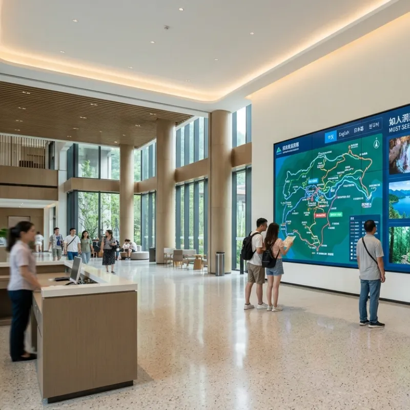
Вывод первый: Передняя структура обслуживания является наиболее ценной, когда задняя часть видеостены не может использоваться в качестве обычного маршрута обслуживания. Это может уменьшить потребность в заднем доступе во время подходящих задач по техническому обслуживанию, но проект по-прежнему требует достаточного переднего рабочего пространства и структуры, предназначенной для подтвержденной конфигурации экрана.
Установки заднего обслуживания могут хорошо работать в диспетчерских, аппаратных или специально построенных помещениях с надлежащим служебным коридором. Они могут обеспечивать удобный доступ к задней части дисплеев, сигнальным соединениям, распределению мощности и структурным компонентам. Однако такой же подход может быть неудобным в розничном магазине, лобби премиум-класса, конференц-зале или утопленной стене, где задняя сторона заблокирована готовой стеной или архитектурным сооружением.
Без запланированной стратегии технического обслуживания будущие сервисные работы могут потребовать от установщика удаления соседних дисплеев, использования лестниц или подъемного оборудования, демонтажа декоративных элементов или временного закрытия части объекта. Эти шаги увеличивают требования к обработке и могут продлить время обслуживания.
Гидравлический кронштейн для переднего обслуживания решает эту проблему доступа через выдвижной или передний механизм открытия. Точная возможность обслуживания зависит от конструкции кронштейна и модели дисплея. Некоторые задачи могут быть выполнены спереди, в то время как другие работы могут по-прежнему требовать доступа к задней части, стороне, контроллеру, распределению питания или инфраструктуре здания.
Вывод первый: Гидравлический кронштейн передн-обслуживания совмещает стен-установленную структуру поддержки, механизм передн-отверстия, пункты установки дисплея, элементы точной регулировки, и запирая систему. Его цель-надежно поддерживать экран, обеспечивая при этом контролируемый доступ на лицевой стороне для утвержденных операций по техническому обслуживанию.
| Термин | Значение в проекте видео стены | Почему это важно |
|---|---|---|
| Переднее обслуживание | Доступ к сервису со смотровой стороны видеостены | Может уменьшить рутинную зависимость от заднего коридора, когда конструкция и панель поддерживают требуемую задачу |
| Поп-вне механизм | Позволяет секции крепления дисплея перемещаться вперед от нормальной плоскости стены | Создание рабочего пространства между панелью и конструкцией стены |
| Гидравлическая помощь | Обеспечивает контролируемое движение и демпфирование при открытии и закрытии | Помогает управлять перемещением нагруженной монтажной секции при использовании в указанном диапазоне |
| Микро-регулировка | Точная регулировка горизонтального, вертикального, глубинного или панельного выравнивания | Поддерживает согласованное положение панели и визуальное выравнивание по стене |
| Механизм блокировки | Удерживает монтажную секцию в закрытом положении | Предотвращает непреднамеренное движение после ввода стены в эксплуатацию |
| Очистка услуг | Пространство, необходимое для безопасного открывания, перемещения троса, инструментов и обработки панелей. | Предотвращает контакт механизма со стенами, кабелями, освещением или соседними структурами. |
Гидравлическая помощь не означает, что установщик может принудительно или свободно перемещать полностью загруженный дисплей без ограничений. Рабочая сила, угол открытия, траектория движения и поддерживаемая нагрузка зависят от выбранной модели, веса панели, центра тяжести, выравнивания установки и условий регулировки.
Вывод первый: Гидравлический кронштейн передн-обслуживания автоматически нет самого лучшего выбора для каждой видео-стены. Это наиболее полезно, когда доступ к заднему обслуживанию ограничен, и проект придает большее значение обслуживанию передней стороны, чем самой низкой первоначальной стоимости монтажа.
| Точка оценки | Фиксированная или задняя структура обслуживания | Гидравлический кронштейн спереди-обслуживания |
|---|---|---|
| Задний доступ | Обычно для обслуживания требуется задний коридор или маршрут доступа | Может снизить рутинные требования к заднему доступу для подходящих задач обслуживания |
| Ограниченный настенный монтаж | Труднее обслуживать, когда задняя сторона заблокирована | Лучше подходит для встраиваемых, готовых или ограниченных пространством установок. |
| Начальная стоимость оборудования | Часто проще и ниже по начальной механической сложности | Может потребовать более высоких первоначальных инвестиций из-за механизмов движения и корректировки |
| Точность установки | Требуется точное выравнивание рамы и регулировка панели | Также требует точного выравнивания; плохое выравнивание может повлиять на движение открытия и посадку панели. |
| Рабочий процесс обслуживания | Может потребоваться оборудование для доступа, задний зазор или удаление прилегающей панели | Может обеспечить определенный маршрут обслуживания на передней стороне при правильной настройке |
| Кабельное управление | Задняя маршрутизация может быть более простой в доступной зоне обслуживания. | Требуются гибкие сервисные петли и контролируемое движение троса вокруг механизма |
| Требования стены | Грузоподъемность и качество крепления остаются критическими | Нагрузка, отладка, жесткость стены, зазор движения, и выравнивание механизма все критические |
| Проект, подходящий лучше всего | Открытое заднее пространство, простой фиксированный дисплей и доступная комната для оборудования | Утопленные, премиум-класса, только для доступа спереди или чувствительные к обслуживанию внутренние установки |
Вывод первый:Не выбирайте гидравлический передний кронштейн для обслуживания, основываясь только на размере диагонали экрана. Совместимость должна быть подтверждена в зависимости от модели дисплея, веса панели, схемы монтажных отверстий, глубины шкафа, центра тяжести, макета и поддерживаемого диапазона кронштейна.
55-дюймовая панель от одного производителя может иметь различную схему монтажа, распределение веса, задний корпус, положение разъема или глубину шкафа от другой 55-дюймовой панели. Поэтому для одного и того же кронштейна могут потребоваться разные крючки, направляющие, проставки или настройки регулировки в зависимости от модели экрана.
Для цитат проекта, обеспечьте модель дисплея, количество экрана, план, размеры стены, фото установки, и предпочитаемый метод обслуживания. Это позволяет просматривать конфигурацию кронштейна перед отправкой, а не обнаруживать ее во время установки.
Вывод первый: Стена и среда обслуживания должны быть проверены перед любым сверлением или обработкой панели начинают. Гидравлический кронштейн может работать только по назначению, когда стена, рама, нагрузка, траектория движения и кабельная трасса подходят для подтвержденного проекта.
Общая нагрузка не должна быть уменьшена до номинального веса дисплея. Проект должен учитывать панели, монтажную конструкцию, кабельные сборки, контрольные принадлежности, факторы безопасности и способ передачи нагрузки на стену. Ответственный установщик или структурный профессионал должны одобрить окончательный метод крепления.
Точный список инструментов зависит от модели кронштейна, подложки стены, конфигурации панели и чертежей проекта. Следующий список является справочным по планированию, а не заменяет утвержденное руководство по установке или процедуру безопасности на площадке.
Перед разметкой стены сравните утвержденную компоновку с фактической моделью дисплея и конфигурацией кронштейна. Подтвердите количество строк и столбцов, ориентацию экрана, вес панели, схему монтажа, опорные направляющие, направление открывания и зазор для технического обслуживания.
Запишите модель панели и модель кронштейна в файл проекта. Если доставленная панель отличается от модели, использованной при проектировании, остановите и запросите проверку совместимости. Не следует считать, что экран аналогичного размера имеет одинаковую геометрию монтажа или распределение нагрузки.
Используйте лазерный нивелир для установления основных горизонтальных и вертикальных опорных линий по всей области видеостены. Отметьте осевую линию, нижнюю ссылку, левую и правую границы и положение каждой скобки в соответствии с утвержденным чертежом.
Не используйте неровный пол, декоративный край стены или линию потолка в качестве единственного эталона. Готовая стена должна быть выровнена с проверенной ссылкой на проект, а не с поверхностью здания, которая уже может быть не на уровне.
Закрепите основную раму или опорные секции к стене с помощью крепежа, одобренного для подтвержденного основания. Если в проекте используется несколько сечений каркаса, установите их в соответствии с утвержденной последовательностью и поддерживайте согласованные горизонтальные и вертикальные ссылки между сечениями.
Перед окончательной затяжкой проверьте общий уровень, отвес, глубину, положение точки крепления и устойчивость рамы. Не используйте чрезмерное усилие болта, чтобы вытянуть искаженную стену или раму на место. Если стена неровная, устраните структурное состояние с помощью утвержденных прокладок, армирования или регулировки рамы, а не принудительного крепления дисплея.
Осмотрите гидравлические компоненты, точки шарнира, оружие, рельсы, замки, ограничительные элементы, точки регулировки и детали защиты транспорта. Убедитесь, что ни один компонент не согнут, не болтается, не загрязнен или не заблокирован.
Перед нагружать дисплеи, испытать механизм без анормалной силы. Движение должно следовать намеченному пути. Если механизм останавливается, скручивается или создает неравномерное сопротивление, проверьте выравнивание и зазоры перед монтажом панелей.
Для многопанельных стен практическая последовательность заключается в том, чтобы начать с нижнего ряда, установить центральную опору и работать наружу, прежде чем двигаться вверх. Точная последовательность должна соответствовать утвержденным чертежам проекта и инструкциям по кронштейну.
При работе с панелями используйте двух техников или подходящее подъемное оборудование. Выровняйте крюки панели или точки крепления с рельсами кронштейна, зацепите опоры и убедитесь, что каждая панель закреплена, прежде чем отпустить нагрузку. Не позволяйте панели повиснуть от кабеля, частично включенного крюка, или разблокированного механизма.
Подключите силовые, сигнальные, контрольные и сетевые кабели в соответствии с планом проводки проекта. Обеспечьте достаточную длину гибкого кабеля для открытия кронштейна без вытягивания разъемов. Контур обслуживания должен быть контролируемым, а не достаточно свободным, чтобы контактировать с движущимися частями, острыми краями или горячими поверхностями.
Медленно открывайте и закрывайте механизм во время первой проверки кабеля. Наблюдайте за каждым кабелем на шарнирах, оружиях, соединителях, и отверстиях рамки. Если какой-либо кабель становится плотным, захваченным, резко согнутым или перетащенным по металлу, остановите и перераспределите его, прежде чем продолжить.
Завершите общее выравнивание рамки перед делать окончательные регулировки панели. Используйте точки регулировки кронштейна & #039;s для исправления горизонтального положения, вертикального положения, глубины и выравнивания передней плоскости. Работа по соседним панелям, а не настройка одной панели по отдельности.
Проверьте результат, используя как физический метод измерения, так и полноэкранный визуальный тест. Равномерный зазор и согласованная передняя плоскость зависят от точности рамы, допуска панели, монтажного оборудования и техники регулировки. Не принуждайте панели вместе, чтобы скрыть проблему с базовой рамой или стеной.
Проверьте выдвижное движение в соответствии с утвержденной рабочей процедурой. Убедитесь, что секция панели открывается равномерно, достигает заданного рабочего положения и не соприкасается со стеной, кабелями, соседними дисплеями, освещением или архитектурной отделкой.
Внимательно закройте секцию и убедитесь, что механизм блокировки полностью задействуется. Проверьте замок после того, как панель находится в нормальном закрытом положении. Частично включенный замок следует рассматривать как проблему установки, а не как приемлемое рабочее состояние.
Включите устройства отображения и протестируйте каждую панель индивидуально перед вводом в эксплуатацию окончательного контента. Подтвердите обнаружение входного сигнала, стабильность сигнала, связь управления, яркость, согласованность цвета и работу контроллера.
Используйте подходящие шаблоны испытаний или утвержденный контент для проверки выравнивания панелей и визуальной однородности. Запишите любой дефектный пиксель, ненормальный шум, потерю сигнала, разницу в цвете или механическую проблему до передачи проекта.
Запишите окончательную компоновку, положения панелей, метки кабелей, настройки регулировки, проверки крепления, фотографии установки, результаты испытаний и открытые элементы. Обеспечьте оператора с инструкциями передн-обслуживания, безопасными отверстиями и заключительным процедурами, очищая наведением, и шагами эскалации для анормалного движения.
Розничная собственность устанавливает стену ЛКД мульти-панели видео-внутри утопленной стены особенности. Дисплей поддержит выдвиженческую связь содержания и свойства, пока окружающая стена получит законченную архитектурноакустическая обработку.
Выемка оставляет недостаточно места для технических специалистов для работы за дисплеем. Удаление архитектурной отделки для каждой задачи обслуживания приведет к нарушению. Проект также требует последовательного выравнивания панели, контролируемого внешнего вида и прокладки кабеля, которая не мешает перемещению монтажного механизма.
Команда установки сперва подтверждает модель панели ЛКД, вес, картину установки, глубину шкафа, субстрат стены, и окончательный план. Затем гидравлическая конструкция для обслуживания передней части оценивается на предмет подтвержденной конфигурации. Рама устанавливается по проверенным опорным линиям, и метод настенного крепления пересматривается для фактической подложки, а не предполагается из размера экрана.
Силовые, сигнальные и контрольные кабели проложены с помощью управляемых служебных петель. Каждый кабель маркируется перед тем, как стена дисплея будет закрыта. Команда завершает выравнивание панелей, регулировку глубины, проверки блокировки, тесты выдвижных окон, тесты сигналов и полноэкранные визуальные проверки до завершения отделки окружающих стен.
Предназначенным результатом является документированный рабочий процесс обслуживания с передним доступом для соответствующих задач обслуживания. В проекте записана окончательная компоновка панели, трассы кабелей, процедура регулировки, операция блокировки и требования к передаче. Это не устраняет все будущие потребности в техническом обслуживании, но снижает зависимость от заднего коридора и дает оператору более четкий метод проверки и обслуживания.
Вывод первый: Большинство проблем с передним обслуживанием должны быть исследованы как вопросы выравнивания, нагрузки, зазора, прокладки кабелей или совместимости, прежде чем сам механизм будет признан неисправным.
| Наблюдаемые симптомы | Возможная причина | Рекомендуемые меры |
|---|---|---|
| Кронштейн открывается не плавно | Смещение рамы, неравномерная нагрузка, помехи в кабеле или проблема с механизмом | Прекратите принуждать механизм; осмотрите уровень, распределение нагрузки, путь кабеля, и зазор движения |
| Зазоры в панели неравномерны | Рама не ровная, точки регулировки несовместимы или панели установлены неправильно | Перед выполнением окончательной регулировки панели проверьте контрольные линии и рамки |
| Панель движется после закрытия | Замок не полностью застегивается или застежки ослаблены | Перед работой проверьте положение блокировки и утвержденную процедуру фиксации. |
| Кабель тянется во время открытия | Недостаточная сервисная петля или кабель, проложенные через подвижное соединение | Раскройте кронштейн только по мере необходимости, изолируйте силу если необходимо, и переурежите кабель с контролируемым допуском движения |
| Экран не заподлицо | Регулировка глубины, посадочные места панели, выравнивание рамы или проблема с монтажным отверстием | Проверьте плоскость рамы, опоры панели, регулировку глубины и подтверждение совместимости. |
| Гидравлическое сопротивление является ненормальным | Перегрузка, смещение, повреждение, загрязнение или работа вне номинального диапазона | Остановите деятельность и свяжитесь ответственная техническая команда для осмотра |
| Экран не запитывает после обслуживания | Потеря мощности, сигнала или управления подключением | Проверьте маркированные соединения, посадочное место разъема, разгрузку от натяжения и утвержденную последовательность питания. |
| Сгибания или сдвиги рамы | Неадекватное настенное основание, крепление, армирование или распределение нагрузки | Остановите загрузку стены и запросите структурный обзор перед продолжением |
⚙️ Полная версия включает параметры крутящего момента, секцию приемки конструкции и журнал установки.
Для международного видео-проекта стены, кронштейн должен быть оценен как часть полного пакета установки. Практический вопрос заключается не только в том, может ли механизм двигаться вперед, но и в том, работают ли выбранная конструкция, дисплей, стена, кабельная трасса, метод обслуживания и документация вместе как одно проектное решение.
Информация о публичной компании Qtenboard описывает бизнес по производству дисплеев с более чем 20-летним опытом глобальной торговли, производственные мощности в Китае, экспорт в более чем 100 стран и поддержку проектов OEM/ODM. Эти возможности актуальны для покупателей проекта, когда они подключены к определенной области: соответствие продукта, проверка конфигурации, проектная документация, упаковка, техническая связь и послепродажные мероприятия.
Для гидравлического проекта кронштейна переднего обслуживания полезные технические результаты могут включать в себя:
Посетите Страница решений для видеостены Qtenboard LCD Для просмотра контекста приложения отображения. Для обсуждения кронштейна для конкретного проекта укажите модель отображения, компоновку, состояние стены, требования к сервисному доступу и целевое расписание установки.
Qtenboard профессиональный изготовитель стены LCD видео-с 20 + летами опыта индустрии, работая 100% принадлежащая собственн производственная база с полными собственными производственными линиями. Производственные мощности компании & #039;s охватывают 330,000m ² и оборудованы с центрами размещения SMT, сборочными линиями LCD, системами тарировки цвета, и 48-часовыми камерами непрерывного испытания вызревания. Обладая сертификатами ISO 9001, CE, FCC, RoHS и UL, компания Qtenboard ежегодно выпускает свыше 500 тысяч дисплейных модулей и обеспечивает реализацию проектов более чем в 100 странах.
Для проекта гидравлического кронштейна переднего обслуживания Qtenboard может обеспечить:
Передний кронштейн для технического обслуживания может уменьшить потребность в обычном заднем доступе для подходящих задач обслуживания, но он не автоматически устраняет все требования заднего доступа. Окончательный метод обслуживания зависит от конструкции кронштейна, модели панели, расположения кабелей, местоположения контроллера, распределения питания и конфигурации проекта.
Совместимость должна быть подтверждена точной моделью дисплея, весом панели, картиной монтажных отверстий, глубиной шкафа, центром тяжести и компоновкой. Не выбирайте кронштейн, основываясь только на размере экрана. Отправьте модель и количество панели для проверки конфигурации перед заказом.
Для установки гипсокартона и полых стен может потребоваться задняя рама из конструкционной стали, армирование или независимая конструкция, поддерживаемая полом. Ответственный установщик или профессионал проекта структурный должны подтвердить субстрат, метод отладки, полную нагрузку, и требования к безопасности перед установкой.
Требуемый зазор зависит от пути открывания кронштейна, глубины панели, угла открывания, задания на обслуживание и рабочего положения техника. Обеспечьте фото места, размеры стены, и выбранную модель панели поэтому проектная группа может рассмотреть требование к зазора.
Сначала проверьте основную раму на уровень, отвес, глубину и устойчивость. После этого подтвердите что каждая панель правильно усажена и используйте одобренные пункты микро-регулировки. Не принуждайте панели совместно или не используйте регулировку панели для того чтобы компенсировать структурно смещенную рамку.
Прекратите форсировать механизм. Проверьте наличие помех в кабеле, неравномерную загрузку панели, смещение рамы, препятствия, зацепление замка, видимые повреждения или работу вне поддерживаемой конфигурации. Если причина не ясна, свяжитесь с ответственной технической командой, прежде чем продолжить.
Кабели должны быть обозначены, защищены и проложены с контролируемыми петлями обслуживания которые позволяют кронштейну раскрыть без вытягивать соединители. Не пропускайте кабели через петли, движущиеся рычаги, точки фиксации или острые края. Окончательный маршрут следует проверять как в открытых, так и в закрытых позициях.
План можно оценить согласно весу панели, картине установки, структуре стены, емкости кронштейна, требованиям к движения, и общему дизайну рамки. 2 × 2, 3 × 3 или более крупный макет должен быть подтвержден как полная конфигурация проекта, а не предполагаться по количеству панелей.
Запросите совместимый список дисплея, монтажные чертежи, фиксируя руководство, требования к обслуживаний-зазора, вспомогательный список, процедуру по установки, инструкции обслуживания, объем гарантии, и проектные примечания конфигурации. Окончательная документация должна соответствовать выбранной модели кронштейна и дисплея.
Основанное на Проект изготовление на заказ можно оценить согласно размерам панели, схеме установки, плану, состоянию стены, необходимом движению, упаковке, документации, и количеству. Отправьте чертежи проекта или информацию о модели экрана, чтобы подтвердить возможный объем.
Гидравлический кронштейн переднего обслуживания должен быть выбран через полный обзор проекта. Модель дисплея, вес панели, схема монтажа, настенная подложка, сервисный зазор, трасса кабеля, окончательная компоновка и рабочий процесс технического обслуживания-все это влияет на правильную конфигурацию.
Чтобы запросить технический обзор, подготовьте: Модель дисплея, размер и вес панели, компоновка видеостены, размеры стены, фотографии объекта, подложка стены, способ установки, доступный задний зазор, необходимый доступ к обслуживанию спереди, страна проекта, количество и целевой график поставки.
Исследуйте Qtenboard LCD видео стены решения | Посетите Qtenboard

CEO | Интерактивный дисплей & Сотрудничество Решение Эксперт
Я являюсь основателем Qtenboard, привнеся более 17 лет практического опыта в индустрию сенсорных дисплеев. Опираясь на перспективы глобального управления, полученные в ходе моих исследований EMBA в Университете Шэньчжэня, я возглавляю свою команду по оптимизации каждого этапа нашей деятельности-от определения продукта до высокоэффективного управления цепочками поставок-гарантируя, что наши производственные возможности остаются на переднем крае отрасли.
Как руководитель Qtenboard, я специализируюсь на предоставлении адаптированных OEM/ODM-решений для интерактивных досок, ЖК-видеостен, цифровых вывесок и сенсорных терминалов промышленного уровня. Опираясь на наш современный промышленный парк площадью 330 000 м² в Шэньчжэне, мы поддерживаем полный контроль жизненного цикла промышленного дизайна, точного производства и тщательного тестирования производительности.
Обладая почти двадцатилетним опытом работы в проектах, решения Qtenboard в настоящее время развернуты в более чем 120 странах и регионах, заслужив доверие более 15 000 корпоративных клиентов по всему миру. Если вы ищете отзывчивого партнера с глубоким учредлением производства для ваших подгонянных проектов дисплея касания, то моя команда и я готовы поддержать ваше зрение с профессиональным передовым опытом.

 ru
ru
 EN
EN  pt
pt  spa
spa  th
th  vie
vie  aze
aze  bel
bel  est
est  lav
lav  ukr
ukr