Instalar uma parede de vídeo LCD não é apenas uma questão de fixar vários monitores em uma parede. A estrutura de montagem determina se a tela pode ser alinhada com precisão, se os cabos permanecem protegidos, se os técnicos podem alcançar os painéis durante a manutenção e se a parede acabada pode ser reparada sem interromper o espaço circundante.
Estas edições tornam-se mais importantes quando uma parede video é instalada em uma parede varejo da mídia, sala de controle, sala de conferência, entrada da recepção, centro de exposição, ou o outro interior terminado onde o acesso traseiro é limitado. Uma estrutura fixa ou de serviço traseiro convencional pode exigir um corredor de manutenção atrás das telas. Em uma parede embutida, sala estreita ou característica arquitetônica embutida, esse espaço pode não existir.
Um suporte hidráulico de manutenção frontal é projetado para projetos em que o acesso de serviço pela frente é uma parte importante do plano de instalação. O mecanismo pode auxiliar o movimento controlado da seção de montagem, enquanto os pontos de ajuste ajudam os instaladores a alinhar a parede do visor durante o comissionamento. No entanto, o suporte deve ser combinado com o modelo de exibição, estrutura da parede, carga total, caminho do cabo e folga de serviço necessária.
Quem é o Qtenboard? A Qtenboard é uma fábrica de origem especializada em soluções de videowall LCD, abrangendo projeto, fabricação, integração de sistemas e suporte de longo prazo. Com mais de 20 anos de experiência em tecnologia de exibição profissional, uma base de fabricação própria de 330 mil m² com linhas de produção internas completas (SMT, montagem de LCD, calibração e testes de envelhecimento) e produtos implantados em mais de 100 países, a Qtenboard oferece sistemas completos de vídeo wall LCD. Para projetos de suporte hidráulico, isso significa um parceiro responsável com processos de fabricação documentados, gerenciamento de qualidade ISO9001, certificações CE/FCC/RoHS e suporte de engenharia específico do projeto.
Este guia foi escrito para integradores de vídeo wall LCD, empreiteiros AV, instaladores de baixa tensão, distribuidores, equipes de propriedades comerciais e gerentes de compras de projetos. Ele explica o que confirmar antes da instalação, como comparar estruturas de manutenção frontal e de serviço traseiro, como instalar e ajustar um suporte hidráulico e o que deve ser incluído em uma lista de verificação prática de entrega.
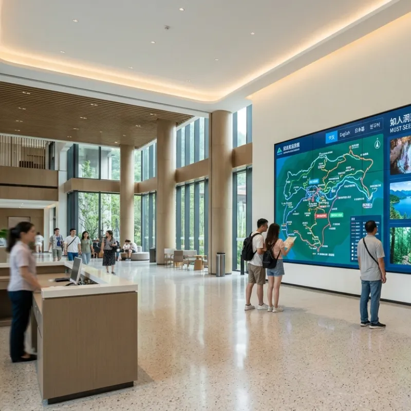
Primeiro, a conclusão: Uma estrutura de manutenção frontal é mais valiosa quando a parte traseira da parede de vídeo não pode ser usada como uma rota de serviço normal. Ele pode reduzir a necessidade de acesso traseiro durante tarefas de manutenção elegíveis, mas o projeto ainda requer espaço de trabalho frontal suficiente e uma estrutura projetada para a configuração da tela confirmada.
As instalações de serviço traseiro podem funcionar bem em salas de controle, salas de equipamentos ou espaços construídos especificamente com um corredor de serviço adequado. Eles podem fornecer acesso conveniente à parte traseira dos monitores, conexões de sinal, distribuição de energia e componentes estruturais. No entanto, a mesma abordagem pode ser inconveniente em uma loja de varejo, lobby premium, sala de reuniões ou parede rebaixada, onde a parte traseira é bloqueada por uma parede acabada ou estrutura arquitetônica.
Sem uma estratégia de manutenção planejada, o trabalho de serviço futuro pode exigir que o instalador remova monitores adjacentes, use escadas ou equipamentos de elevação, desmonte elementos decorativos ou feche temporariamente parte da instalação. Essas etapas aumentam os requisitos e podem estender o tempo do serviço.
Um suporte hidráulico de manutenção frontal aborda esse desafio de acesso através de um mecanismo de abertura frontal ou de abertura frontal. A capacidade exata do serviço depende do projeto do suporte e do modelo da exposição. Algumas tarefas podem ser concluídas pela frente, enquanto outros trabalhos ainda podem exigir acesso à infraestrutura traseira, lateral, controladora, distribuição de energia ou do edifício.
Primeiro, a conclusão: Um suporte hidráulico de manutenção frontal combina uma estrutura de suporte montada na parede, um mecanismo de abertura frontal, pontos de montagem do visor, elementos de ajuste fino e um sistema de travamento. Sua finalidade é apoiar firmemente a tela ao permitir o acesso dianteiro controlado para operações de manutenção aprovadas.
| Prazo | Significado em um projeto Video Wall | Por que é importante |
|---|---|---|
| Manutenção frontal | Acesso ao serviço do lado de visualização da parede de vídeo | Pode reduzir a dependência rotineira em um corredor traseiro quando a estrutura e o painel apoiam a tarefa exigida |
| Mecanismo pop-out | Permite que uma seção de montagem do visor avance do plano normal da parede | Cria espaço entre o painel e a estrutura da parede |
| Assistência hidráulica | Fornece movimento controlado e amortecimento durante a abertura e fechamento | Ajuda a gerenciar o movimento da seção de montagem carregada quando usada dentro do intervalo especificado |
| Micro-ajuste | Ajuste fino do alinhamento horizontal, vertical, de profundidade ou do painel | Suporta posição consistente do painel e alinhamento visual através da parede |
| Bloqueio do mecanismo | Mantém a seção de montagem segura na posição fechada | Impede o movimento indesejado após a parede ser comissionada |
| Apuramento do serviço | O espaço necessário para a abertura segura, o movimento do cabo, as ferramentas e o manuseio do painel | Impede que o mecanismo entre em contato com paredes, cabos, iluminação ou estruturas vizinhas |
A assistência hidráulica não significa que o instalador possa forçar ou reposicionar livremente um monitor totalmente carregado sem limites. A força operacional, o ângulo de abertura, o caminho do movimento e a carga suportada dependem do modelo selecionado, peso do painel, centro de gravidade, alinhamento da instalação e condição de ajuste.
Primeiro, a conclusão: Um suporte hidráulico da frente-manutenção não é automaticamente a melhor escolha para cada parede video. É mais útil quando o acesso de serviço traseiro é restrito e o projeto coloca um valor maior na manutenção frontal do que no menor custo de montagem inicial.
| Ponto Avaliação | Estrutura fixa ou traseira de serviço | Suporte hidráulico de manutenção frontal |
|---|---|---|
| Acesso traseiro | Geralmente requer corredor traseiro ou rota de acesso para serviço | Pode reduzir os requisitos rotineiros de acesso traseiro para tarefas de manutenção elegíveis |
| Instalação parede restrita | Mais difícil de manter quando o lado traseiro está bloqueado | Mais adequado para instalações embutidas, acabadas ou com espaço limitado |
| Custo inicial do hardware | Muitas vezes mais simples e menor na complexidade mecânica inicial | Pode exigir um maior investimento inicial devido a mecanismos de movimento e ajuste |
| Instalação Precisão | Requer alinhamento preciso do quadro e ajuste do painel | Também requer alinhamento preciso; nivelamento pobre pode afetar a abertura do movimento e ajuste do painel |
| Fluxo manutenção | Pode exigir equipamento de acesso, folga traseira ou remoção do painel adjacente | Pode fornecer uma rota de manutenção frontal definida quando configurado corretamente |
| Gestão do cabo | O roteamento traseiro pode ser mais direto em uma área de serviço acessível | Requer circuitos flexíveis e movimento controlado do cabo ao redor do mecanismo |
| Exigências do muro | A capacidade de carga e a qualidade permanecem críticas | Carga, fixação, rigidez da parede, folga de movimento e alinhamento do mecanismo são críticos |
| Projeto Best-fit | Espaço traseiro aberto, exposição fixa simples, e sala acessível do equipamento | Instalações interiores embutidas, premium, apenas de acesso frontal ou sensíveis à manutenção |
Primeiro, a conclusão:Não selecione um suporte hidráulico de manutenção frontal baseado apenas no tamanho diagonal da tela. A compatibilidade deve ser confirmada de acordo com o modelo de exibição, peso do painel, padrão de furo de montagem, profundidade do gabinete, centro de gravidade, layout e o suporte & #039;s faixa suportada.
Um painel de 55 polegadas de um fabricante pode ter um padrão de montagem diferente, distribuição de peso, caixa traseira, posição do conector ou profundidade do gabinete de outro painel de 55 polegadas. O mesmo suporte pode, portanto, exigir diferentes ganchos, trilhos, espaçadores ou configurações de ajuste, dependendo do modelo da tela.
Para citações do projeto, forneça o modelo da exposição, a quantidade da tela, a disposição, as dimensões da parede, as fotos da instalação, e o método preferido da manutenção. Isso permite que a configuração do suporte seja revisada antes do envio, em vez de descoberta durante a instalação.
Primeiro, a conclusão: A parede e o ambiente do serviço devem ser verificados antes que toda a perfuração ou manipulação do painel comece. Um suporte hidráulico só pode executar como pretendido quando a parede, quadro, carga, caminho de movimento e rota do cabo são adequados para o projeto do projeto confirmado.
A carga total não deve ser reduzida ao peso nominal do mostrador. O projeto deve levar em conta os painéis, a estrutura de montagem, os conjuntos de cabos, os acessórios de controle, os fatores de segurança e a maneira como a carga é transferida para a parede. O instalador responsável ou profissional estrutural deve aprovar o método de fixação final.
A lista exata de ferramentas depende do modelo do suporte, do substrato da parede, da configuração do painel e dos desenhos do projeto. A lista a seguir é uma referência de planejamento e não um substituto do manual de instalação aprovado ou do procedimento de segurança do local.
Antes de marcar a parede, compare o layout aprovado com o modelo de exibição real e a configuração do suporte. Confirme o número de linhas e colunas, a orientação da tela, o peso do painel, o padrão de montagem, os trilhos de suporte, a direção de abertura e a folga de manutenção.
Grave o modelo do painel e o modelo do colchete no arquivo do projeto. Se o painel fornecido diferir do modelo usado durante o projeto, pare e solicite uma revisão de compatibilidade. Não presuma que uma tela semelhante tenha a mesma geometria de montagem ou distribuição.
Use um nível laser para estabelecer as principais linhas de referência horizontais e verticais em toda a área do videowall. Marque a linha central, a referência inferior, os limites esquerdo e direito e cada posição do suporte de acordo com o desenho aprovado.
Não use um piso irregular, borda de parede decorativa ou linha de teto como única referência. A parede acabada deve ser alinhada a uma referência de projeto verificada, não a uma superfície de construção que já esteja fora de nível.
Fixe as seções do quadro principal ou do apoio à parede usando os prendedores aprovados para a carcaça confirmada. Se o projeto usar várias seções do quadro, instale-as de acordo com a sequência aprovada e mantenha referências horizontais e verticais consistentes entre as seções.
Antes do aperto final, verifique o nível geral, o prumo, a profundidade, a posição do ponto de fixação e a estabilidade do quadro. Não use força excessiva do parafuso para puxar uma parede distorcida ou enquadrar na posição. Se a parede é desigual, resolva a condição estrutural com os calços aprovados, o reforço, ou o ajuste do quadro um pouco do que forçando as montagens da exposição.
Inspecione os componentes hidráulicos, pontos de dobradiça, braços, trilhos, travas, elementos limite, pontos de ajuste e peças de proteção do transporte. Confirme se nenhum componente está dobrado, solto, contaminado ou obstruído.
Antes de carregar as telas, teste o mecanismo sem força anormal. O movimento deve seguir o caminho pretendido. Se o mecanismo parar, torcer ou criar resistência irregular, inspecione o alinhamento e as folgas antes de montar os painéis.
Para paredes de vários painéis, uma sequência prática é começar com a linha inferior, estabelecer a referência central e trabalhar para fora antes de subir. A sequência exata deve seguir os desenhos aprovados do projeto e as instruções do suporte.
Use dois técnicos ou equipamentos de elevação adequados ao manusear painéis. Alinhe os ganchos ou pontos de montagem do painel com os trilhos do suporte, engaje os suportes e confirme que cada painel está preso antes de liberar a carga. Não permita que o painel fique pendurado em um cabo, gancho parcialmente engatado ou mecanismo desbloqueado.
Conecte cabos de energia, sinal, controle e rede de acordo com o plano de fiação do projeto. Forneça o comprimento do cabo flexível suficiente para que o suporte abra sem puxar os conectores. O circuito de serviço deve ser controlado em vez de solto o suficiente para entrar em contato com partes móveis, bordas afiadas ou superfícies quentes.
Abra e feche o mecanismo lentamente durante a primeira verificação do cabo. Observe cada cabo nas dobradiças, braços, conectores e aberturas do quadro. Se algum cabo ficar apertado, preso, acentuadamente dobrado ou arrastado pelo metal, pare e reencaminhe-o antes de continuar.
Termine o nivelamento total do quadro antes de fazer ajustes finais do painel. Use os pontos de ajuste do suporte para corrigir a posição horizontal, a posição vertical, a profundidade e o alinhamento do plano frontal. Trabalhe em painéis adjacentes em vez de ajustar um painel isoladamente.
Verifique o resultado usando um método de medição física e um teste visual em tela cheia. Um espaço uniforme e plano dianteiro consistente dependem da precisão do quadro, tolerância do painel, hardware de montagem e técnica de ajuste. Não force os painéis juntos para esconder um problema de moldura ou parede.
Teste o movimento de saída de acordo com o procedimento operacional aprovado. Confirme se a seção do painel abre uniformemente, atinge a posição de serviço pretendida e não entra em contato com a parede, cabos, displays vizinhos, iluminação ou acabamentos arquitetônicos.
Feche a seção cuidadosamente e confirme se o mecanismo de bloqueio está totalmente engatado. Teste o bloqueio depois que o painel estiver em sua posição normal fechada. Um bloqueio parcialmente engatado deve ser tratado como um problema de instalação, não como uma condição operacional aceitável.
Ligue as unidades de exibição e teste cada painel individualmente antes do comissionamento final do conteúdo. Confirme a detecção da entrada, a estabilidade do sinal, a comunicação do controle, o brilho, a consistência da cor, e a operação do controlador.
Use padrões de teste adequados ou conteúdo aprovado para inspecionar o alinhamento do painel e a uniformidade visual. Registre qualquer pixel defeituoso, ruído anormal, perda de sinal, diferença de cor ou problema mecânico antes da entrega do projeto.
Registre o layout final, posições do painel, etiquetas do cabo, configurações de ajuste, verificações de fixação, fotografias da instalação, resultados do teste e itens abertos. Forneça ao operador instruções de manutenção frontal, procedimentos seguros de abertura e fechamento, orientação de limpeza e etapas de escalonamento para movimentos anormais.
Uma propriedade de varejo está instalando uma parede video do LCD do multi-painel dentro de uma parede recessed do recurso. A exposição apoiará o conteúdo promocional e a comunicação da propriedade, quando a parede circunvizinha receber um tratamento arquitetónico terminado.
O recesso deixa espaço insuficiente para os técnicos trabalharem atrás da tela. Remover o acabamento arquitetônico para cada tarefa de serviço criaria interrupção. O projeto também requer alinhamento consistente do painel, uma aparência frontal controlada e roteamento de cabos que não interfira no movimento do mecanismo de montagem.
A equipe da instalação confirma primeiramente o modelo do painel do LCD, o peso, o teste padrão da montagem, a profundidade do armário, a carcaça da parede, e a disposição final. Uma estrutura hidráulica de manutenção frontal é então avaliada para a configuração confirmada. O quadro é instalado contra linhas de referência verificadas e o método de fixação da parede é revisado para o substrato real em vez de assumir o tamanho da tela.
Cabos de energia, sinal e controle são roteados com loops de serviço controlados. Cada cabo é rotulado antes que a parede do visor seja fechada. A equipe completa o alinhamento do painel, ajuste de profundidade, verificações de travamento, testes pop-out, testes de sinal e verificações visuais em tela cheia antes que o acabamento da parede ao redor seja finalizado.
O resultado pretendido é um workflow documentado da manutenção do front-access para tarefas elegíveis do serviço. O projeto registra o layout final do painel, as rotas do cabo, o procedimento de ajuste, a operação do bloqueio e os requisitos de entrega. Isso não elimina todas as necessidades futuras de manutenção, mas reduz a dependência de um corredor traseiro e dá ao operador da propriedade um método mais claro para inspeção e serviço.
Primeiro, a conclusão: A maioria dos problemas de manutenção frontal deve ser investigada como problemas de alinhamento, carga, folga, roteamento de cabos ou compatibilidade antes que o próprio mecanismo seja considerado defeituoso.
| Sintoma Observado | Causa Possível | Ação recomendada |
|---|---|---|
| O suporte não abre suavemente | Desalinhamento do quadro, carga irregular, interferência do cabo ou problema do mecanismo | Pare de forçar o mecanismo; inspecione o nível, a distribuição da carga, o trajeto do cabo, e o afastamento do movimento |
| As lacunas do painel são desiguais | O quadro não está nivelado, os pontos de ajuste são inconsistentes ou os painéis não estão sentados corretamente | Verifique as linhas de referência e o quadro antes do ajuste final do painel |
| Painel move após o fechamento | Bloqueio não está totalmente envolvido ou fixadores estão soltos | Verifique a posição de bloqueio e o procedimento aprovado antes do funcionamento |
| O cabo é puxado durante a abertura | Laço ou cabo insuficiente do serviço distribuído através de uma junção movente | Abra o suporte somente como necessário, isole o poder se necessário, e reencaminhe o cabo com permissão controlada do movimento |
| A face do ecrã não está nivelada | Ajuste de profundidade, assento do painel, alinhamento do quadro ou problema do furo de montagem | Verifique o plano do quadro, os suportes do painel, o ajuste de profundidade e a compatibilidade confirmada |
| A resistência hidráulica é anormal | Sobrecarga, desalinhamento, dano, contaminação ou operação fora da faixa nominal | Pare a operação e contate a equipe técnica responsável para inspeção |
| A tela não liga após a manutenção | Ligação solta do poder, do sinal, ou do controle | Verifique as conexões rotuladas, o assento do conector, o alívio de tensão e a sequência de potência aprovada |
| Quadro flexiona ou desloca | Substrato de parede inadequado, fixação, reforço ou distribuição de carga | Pare o carregamento e solicite revisão estrutural antes de continuar |
⚙️ A versão completa inclui parâmetros de torque, uma seção de aceitação estrutural e um log de instalação.
Para um projeto internacional do vídeo wall, o suporte deve ser avaliado como parte do pacote completo da instalação. A questão prática não é apenas se o mecanismo pode avançar, mas se a estrutura selecionada, display, parede, rota do cabo, método de manutenção e documentação trabalham juntos como uma solução de projeto.
Qtenboard & #039;s informações empresa pública descreve um negócio de exibição de fabricação com mais de 20 anos de experiência em comércio global, instalações de fabricação na China, as exportações para mais de 100 países, e OEM/ODM apoio ao projecto. Esses recursos são relevantes para os compradores do projeto quando eles estão conectados a um escopo definido: correspondência de produtos, revisão de configuração, documentação do projeto, embalagem, comunicação técnica e acordos pós-venda.
Para um projeto de suporte hidráulico de manutenção frontal, os resultados técnicos úteis podem incluir:
Visite o Qtenboard LCD Video Wall soluções página Para revisar o contexto do aplicativo exibir. Para uma discussão de suporte específica do projeto, forneça o modelo de exibição, o layout, a condição da parede, o requisito de acesso ao serviço e o cronograma de instalação alvo.
Qtenboard é um fabricante de vídeo wall LCD profissional com 20 + anos de experiência na indústria, operando uma base de fabricação 100% própria com linhas de produção internas completas. As instalações fabris da empresa abrangem 330 mil m² e estão equipadas com centros de colocação SMT, linhas de montagem LCD, sistemas de calibração de cores e câmaras de teste de envelhecimento contínuo de 48 horas. Com certificações ISO9001, CE, FCC, RoHS e UL, a Qtenboard produz mais de 500.000 unidades de exibição anualmente e apoia a implantação de projetos em mais de 100 países.
Para um projeto de suporte hidráulico de manutenção frontal, a Qtenboard pode fornecer:
Um suporte de manutenção frontal pode reduzir a necessidade de acesso traseiro de rotina para tarefas de serviço elegíveis, mas não elimina automaticamente todos os requisitos de acesso traseiro. O método de manutenção final depende do design do suporte, modelo do painel, arranjo do cabo, localização do controlador, distribuição de energia e configuração do projeto.
A compatibilidade deve ser confirmada pelo modelo exato da exposição, peso do painel, teste padrão do montagem-furo, profundidade do armário, centro de gravidade, e disposição. Não selecione um colchete baseado apenas no tamanho da tela. Envie o modelo e a quantidade do painel para uma revisão da configuração antes do pedido.
As instalações de drywall e parede oca podem exigir uma estrutura traseira de aço estrutural, reforço ou uma estrutura independente apoiada no piso. O instalador responsável ou o profissional estrutural do projeto deve confirmar o substrato, o método de fixação, a carga total e os requisitos de segurança antes da instalação.
A folga necessária depende do caminho de abertura do suporte, profundidade do painel, ângulo de abertura, tarefa de serviço e posição de trabalho do técnico. Forneça fotos do local, dimensões da parede e o modelo de painel selecionado para que a equipe do projeto possa revisar o requisito de folga.
Primeiro, verifique o quadro principal para nível, prumo, profundidade e estabilidade. Em seguida, confirme se cada painel está corretamente assentado e use os pontos de microajuste aprovados. Não force os painéis juntos ou use o ajuste do painel para compensar um quadro estruturalmente desalinhado.
Pare forçando o mecanismo. Verifique se há interferência do cabo, carga desigual do painel, desalinhamento do quadro, obstrução, engate do fechamento, dano visível, ou operação fora da configuração apoiada. Se a causa não for clara, contate a equipe técnica responsável antes de continuar.
Os cabos devem ser rotulados, protegidos e roteados com loops de serviço controlados que permitem que o suporte abra sem puxar conectores. Não passe cabos por dobradiças, braços móveis, pontos de travamento ou bordas afiadas. A rota final deve ser verificada durante as posições aberta e fechada.
O layout pode ser avaliado de acordo com o peso do painel, padrão de montagem, estrutura da parede, capacidade do suporte, requisitos de movimento e design geral do quadro. Um layout 2 × 2, 3 × 3 ou maior deve ser confirmado como uma configuração completa do projeto, em vez de assumido apenas pelo número de painéis.
Solicite a lista de exibição compatível, desenhos de montagem, orientação de fixação, requisitos de limpeza, lista de acessórios, instruções de manutenção, escopo de garantia e notas de configuração específicas do projeto. A documentação final deve corresponder ao modelo de suporte e exibição selecionado.
A personalização baseada no projeto pode ser avaliada de acordo com as dimensões do painel, padrão de montagem, layout, condição da parede, movimento necessário, embalagem, documentação e quantidade. Envie os desenhos do projeto ou informações do modelo da tela para confirmar o escopo viável.
Um suporte hidráulico de manutenção frontal deve ser selecionado através de uma revisão completa do projeto. O modelo do visor, o peso do painel, o padrão de montagem, o substrato da parede, a folga do serviço, a rota do cabo, o layout final e o fluxo de trabalho de manutenção afetam a configuração correta.
Para solicitar uma revisão técnica, prepare: Modelo de exibição, tamanho e peso do painel, layout de vídeo wall, dimensões da parede, fotografias do site, substrato da parede, método de instalação, folga traseira disponível, acesso necessário ao serviço frontal, país do projeto, quantidade e cronograma de entrega.
Explore as soluções Qtenboard LCD Video Wall | Visitar Qtenboard

CEO | Display interativo e solução colaboração Expert
Eu sou o fundador da Qtenboard, trazendo mais de 17 anos de experiência prática para a indústria de telas sensíveis ao toque. Com base na perspectiva de gestão global adquirida através dos meus estudos EMBA na ShenZhen University, lidero minha equipe na otimização de todas as etapas de nossas operações-desde a definição do produto até o gerenciamento da cadeia de suprimentos de alta eficiência-garantindo que nossas capacidades de fabricação permaneçam na vanguarda do setor.
Como líder da Qtenboard, sou especialista em fornecer soluções OEM/ODM personalizadas para quadros interativos, paredes de vídeo LCD, sinalização digital e terminais de toque de nível industrial. Apoiados por nosso parque industrial moderno de 330.000 m² em Shenzhen, mantemos controle de ciclo de vida completo sobre design industrial, fabricação de precisão e testes rigorosos de desempenho.
Com quase duas décadas de experiência em projetos, as soluções de exibição da Qtenboard estão implantadas em mais de 120 países e regiões, conquistando a confiança de mais de 15.000 clientes corporativos em todo o mundo. Se você está procurando um sócio responsivo com uma fundação profunda da fabricação para seus projetos personalizados da exposição do toque, minha equipe e eu estamos prontos para apoiar sua visão com excelência profissional.

 pt
pt
 EN
EN  spa
spa  th
th  vie
vie  aze
aze  bel
bel  est
est  lav
lav  ukr
ukr  ru
ru